
Inhaltsverzeichnis
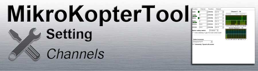
Function - Channel

The FlightCtrl can manage up to 16 channels.
Channels 1-4 are already preset for GAS (1), GIER (4), NICK (3) and ROLL (2).
This corresponds to "Mode2" on the remote control (see instructions Remote control).
If you move one of the control sticks on the remote control, the corresponding bar display beside the cannel moves.
The beam deflection should be the same as the joystick movement.
If this is opposite, the corresponding channel in the transmitter must be inverted.
In addition, 8 "POTI" are available.
Either channels, serial channels or a fixed value such as WP event, minimum, middle, maximum can be set on each "POTI".
What is a "POTI"?
An encoder is assigned to each channel on the remote control (stick, switch, push button, slider) zugeteilt.
Depending on the encoder position, a value is transferred. A "POTI" then transmits the value of the channel.
There are various functions on the MikroKopter such as PositionHold, AltitudeControl, switch LEDs or trigger.
Some functions (e.g. AltitudeControl) can be assigned a channel for switching ON / OFF directly.
Other functions can either be assigned a fixed value or a "POTI".
The "POTI" transmits the value that the channel assigned to it is currently delivering.Example:
LEDs are to be connected and controlled at switching output 2.
Under "Out2 Timing" you can set a number from 0-247 or a "POTI".
The LEDs can then:flash continuously at a fixed interval
(INFO: the flashing interval can also be set using the boxes in the "bit mask")Under "Out2 Timing" you have set a number between 1 and 247
- The number now determines the ON/OFF switching duration in ms per bit mask box
- be switched ON / OFF
Under "Out2 Timing" a "POTI" is set and
a 2-way switch is assigned to this channel on the remote control.
If the switch is OFF the switching output 2 is also off (no matter how the bit mask is set)
If the switch is ON the switching output is permanently on (no matter how the bit mask is set)
- Manually control the flashing interval using the remote control
Under "Out2 Timing" a "POTI" is set and
this channel is assigned to a slide control on the remote control.
- Depending on the position of the slide, the switching output is switched faster or slower. The transmitted number now determines the ON / OFF switching duration in m / s per bit mask box
Channel 1-16

The function of the 16 usable channels can be checked here with the bar graph.
Below the bar you can see the respective channel, above the bar the transmitted value.
If an encoder is operated on the remote control (Stick, switch, push button, slider), the corresponding bar moves.
When checking a channel, the value above the bar should be:0 (channel OFF)
127 (Channel centered)
254 (channel ON)
If the value is less than 247 (if the used encoder is ON) or greater than 0 (if the used encoder is OFF), functions of the copter cannot be carried out correctly or only partially.
The channel deflection (servo travel) can be set in the remote control.
(please see manual of the used transmitter)
Serial Channel 1-12

The FlightCtrl can also evaluate up to 12 serial channels (e.g. via joystick).
These serial channels can also be assigned functions and "POTI".
For example a camera holder can be controlled via this.
 These serial channels cannot be assigned to the control functions (throttle, yaw, nick, roll).
To be able to use these additional serial channels,:- there must be a connection between the copter and the PC
(This connection can e.g. be made via RangeExtender)
The KopterTool must be open for use!
- A joystick (or other controller) is installed on the PC for control
- there must be a connection between the copter and the PC


The connected joystick (controller) must be assigned to the serial channels.
The menu required for this is opened in the KopterTool via the button ass Serial Channels.
Using the selection fields on the right, the individual encoders can be assigned to the serial channels by the joystick.
So that the serial channels are also transferred to the copter, a check mark must be placed below Send the serial channels active.
Motor safety switch

The MikroKopter motors can be started / stopped in 4 different ways.
Switching on / off via a stick without safety function
(In this way, motors can easily be switched off accidentally during flight!)- Switch on / off via certain positions of both sticks
- Switching on / off via stick with additional push button
- Switching on / off via stick with additional button
The setting under Motor safety switch determines how the motors are switched on / off:
OFF
Start engines => throttle down + yaw right
Stop engines => throttle down + yaw left
Inaktiv
Start engines => throttle down + yaw right plus Nick down + Roll left or right
Stop engines => throttle down + yaw left plus Nick down + Roll left or right
Ch xx
- The channel entered here is assigned to a push button on the remote control
- This channel is inverted on the remote control so that when the button is not pressed, the channel is switched (254).
Start engines => Press the push button and hold it plus throttle down + yaw right
Stop engines => Press the push button and hold it plus throttle down + yaw left
Ch xx + hook at engine start / stop
- The channel entered here is assigned to a 2-way switch on the remote control
Start engines => throttle down then move 2-way switch to position ON
Stop engines => throttle down then move 2-way switch to position OFF
(The 2-way switch has no function if the gas stick is not at the bottom!)
Select receiver

The remote control system used can be selected under Select receiver.
How the receivers are connected to the FlightCtrl is described here: Link
You can set here:
Multisignal (PPM)
35MHz receiver (for e.g. receiver ACT DSL4 top or 2.4GHz-receiver R6107SP)
Spektrum Satellit
2.4GHz Spectrum satellite receiver
Spektrum Satellit (HIRES)
2.4GHz Spectrum satellite receiver with high resolution (2048) (e.g. DSX7, DX8, DSX9, DSX12)
Spektrum Satellit (LowRES)
2.4GHz Spectrum satellite receiver with low resolution (512) (e.g. used with some Spectrum plug-in modules)
Jeti Satellit
2.4GHz Jeti Satellit receiver (e.g. RMK2)
With this setting, the telemetry output for Jeti is also activated.
The telemetry of the MikroKopter is displayed on the Jeti Box.
ACT DSL
Connection of an ACT DSL signal to the 2nd serial interface of the FlightCtrl
Graupner HoTT
2.4GHz Graupner HoTT receiver (e.g. GR-12, GR-16, GR-24)
With this setting, the telemetry output for Graupner is also activate.
The telemetry of the MikroKopter is shown in the display of the transmitter.
Futaba S.BUS
2.4GHz Futaba S.BUS receiver
A signal inverter is required to connect a S.BUS receiver to the FlightCtrl (Shoplink).
MULTIPLEX
2.4GHz MULTIPLEX receiver (MULTIPLEX RX-4/16 FLEXX or RX-7-DR M-LINK)
Note:
- The PPM and telemetry cables of the FlightCtrl must be connected
- NO telemetry data is transmitted!
- The output at the B / D socket of the receiver must be switched to digital servo data (SRXL) with the PC software 'Multiplex Launcher'.
User
- Free for programmers
Telemetry: Speak all events
With this setting you can choose whether all telemetry events should be announced (warnings and some functions).
If the function is deactivated here, only warning messages are announced automatically.
INFO
A telemetry display and announcement is only possible with a suitable Jeti or Graupner HoTT remote control.
Other remote controls are NOT supported.
For remote controls without voice output / without loudspeakers (e.g. Graupner MX-20), the function should be deactivated here.
In order for the correct announcements to be output, an adapted voice file must be used for the respective remote control.
The appropriate language files and help for each station can be found here:

