
Inhaltsverzeichnis
Servo out 1-5

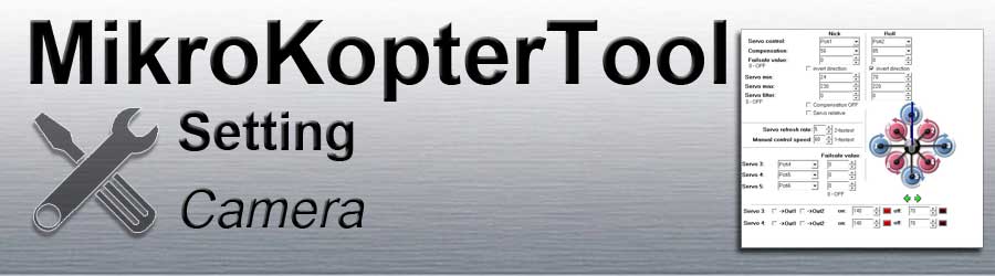
Die folgenden Einstellungen betreffen die Servoausgänge 1 bis 5 der FlightCtrl.
Servo out 1 => Servo control Nick - (camera gimbal Nick)
Servo out 2 => Servo control Roll - (camera gimbal Roll)
Servo out 3 => Servo 3
Servo out 4 => Servo 4
Servo out 5 => Servo 5
(Servo out 6 => FlightCtrl V3.0 - not in use)
!!! The servo outputs are only functional after calibration / activation of the copter !!!
=> Activation: throttle up + yaw left
Servo control

The servo outputs 1 + 2 are intended for the control of a camera holder.
(Servo-Gimbal or Brushless-Gimbal)
These can be set here specifically.
Servo outputs 1 + 2 are set here.Servo control Nick => Servo out 1
Servo control Roll => Servo outg 2

The control of a gimbal for nick and roll can be connected to these outputs.
Either a POTI or a fixed value (0-247) can be entered as the value.
- POTI
If a channel on the remote control is assigned to a slider on the transmitter, the associated POTI in the KopterTool can be entered here.
If the slider on the remote control is moved, the connected servo moves into the respective position.
- Fix value
- If a fixed value is entered, the connected servo moves to the set position.
- POTI
Compensation
In flight, the pitch and roll servo on the servo gimbal is automatically compensated for by the 'Compensation'.
The automatic compensation can be adapted to the connected servo using the entered value.

If you set here a "0", there is no compensation and the servo remains in the set position.


If the value is set too high, the adjustment is too large ...


.. and if the value is too low, the adjustment is too small.


Failsafe value
Failsafe value
Servo value that the pitch or roll servo approaches if the receiver signal is lost.
- 0 = OFF (Function deactivated)
- 1-247 = Servo value
- To determine the required servo value, move the servo to the desired position using the remote control. The value for the corresponding channel can now be viewed in the bar graph ~ - (bottom bar) - ~.


Invert direction
- If the direction of rotation of the servos on the camera holder is the wrong way round, the direction for nick and roll can be inverted here.
Servo / Min / Max / Filter


Some servos tend to move in the opposite direction at the end stop.
With servo min / max the servo travel for the pitch and roll servo can be restricted.
Servo min/max
- Minimum value and maximum value as a stop.
Servo filter
This value can be set from 0 - 25. Depending on the input, the servos are controlled softer (5-20) or harder (0-4).
Why this parameter? If the camera gimbal is mechanically decoupled by rubber dampers, the camera gimbal moves to the remaining MK in a damped manner. If the MK was moved, the FC would now try to compensate for these movements quickly using servos - even those that would not have arrived at the camera mount. In principle, this parameter now simulates this damping so that the servos do not react to every small twitch of the MK.
Compensation OFF

Here you can switch through servo outputs 1 + 2 as direct servo outputs.
This will e.g. needed for brushless gimbals.
If you activate this function, the automatic compensation for servo gimbals is deactivated.
Servo relative
If this function is deactivated, the movement of the servo is the same as the adjustment of the slider on the remote control.
If this function is activated, the middle position of the slider on the transmitter is the rest position => the servo does not move.
If you move the slider from the middle position in one direction or the other, the servo also moves in the corresponding direction.
If the slider is back in the middle position, the servo stops at the new position.
For example, the camera inclination on the gimbal can also be controlled by a slider with a spring.
Servo refresh rate

The "Servo refresh rate" limits the number of maximum output servo channels.
If you reduce the input to "3", only servo outputs 1, 2 and 3 are activated. The servo outputs Servo 4 and 5 are then deactivated.
Manual control speed
The control of the pitch / roll servo can be damped via the remote control using the value entered here.
So slower / softer servo movements are also possible.
A number from 0-247 can be entered here.
0 => The servo cannot be controlled via the entered POTI
1 => Direct control of the servo (you can use this if you connect a Brushless-Gimbals)
2-247 => Damping the control of the servo (recommended value = 60)
Servo 3-4-5

The servo outputs 3, 4, 5 can be set here.
Either a POTI or a fixed value (0-247) can be entered as the value.
- POTI
If a channel on the remote control is assigned to a slider on the transmitter, the associated POTI in the KopterTool can be entered here.
If the slider on the remote control is moved, the connected servo moves into the respective position.
- Fix value
- If a fixed value is entered, the connected servo moves to the set position.
- POTI
Failsafe value
Failsafe value
Servo value that the pitch or roll servo approaches if the receiver signal is lost.
- 0 = OFF (Function deactivated)
- 1-247 = Servo value
- To determine the required servo value, move the servo to the desired position using the remote control. The value for the corresponding channel can now be viewed in the bar graph ~ - (bottom bar) - ~.


Servo 3-4 / Out 1-2

Here the servo outputs 3/4 can be assigned to one of the switching outputs Out1/Out2.
With the values for "on" and "off" (value between 0-247), functions of the electronics connected to servo output 3 + 4 can then be determined.
Via the switching outputs, the servo outputs 3/4 can then e.g. receive permanent switching intervals. Or automatically trigger on waypoint flight.
Example:
A servo or controller* is connected to servo output 3
(*e.g. IR-Ctrl or CamCtrl Servo)- A push button on the remote control was assigned a channel. A camera is to be triggered via this channel
- The camera should also trigger automatically when the waypoints are flown
Since the switching output 1 is automatically controlled during the waypoints flight, we enter the assigned channel (POTI) from the button here.
The servo / controller is now connected to servo output 3 and we tick Servo3 -> Out1.
Now we need the switching states for on => Function trigger and off => no function.
A number from 0-247 can be entered as the value. The values are:0 => Channel not switched
v
127 => Channel centered
v
247 => Channel fully switched
- Switch positions would be e.g. :
[en/IR-Ctrl|IR-Ctrl]]
0 => Function 1 of IR-Ctrl (channel not switched)
127 => no function (channel centered)
247 => Function 2 of IR-Ctrl (Channel fully switched)CamCtrl __Servo__
0 => no function (Channel not switched)
127 => Function 1 - Trigger (Channel centered)
247 => Function 2 - REC (Channel fully switched)Servo
OFF => 127 (Channel centered = center Servo)
ON => 137 (Servo moves a little bit clockwise)
The shortest possible path should be set for a servo.
If the values are far apart, a servo will maybe not move.
If the first function should now be used, the following would be entered in the IR-Ctrl: on=0 and off=127
And with the CamCtrl these values: on=127 and off=0. For a Servo e.g. on=137 und off=127.
If you press the push button on the remote control, this function is switched / the servo is moved.
Alignment

Is only required if the alignment is also adjusted in the Mixer-SETUP.
This would be e.g. necessary to adjust the flight direction if the! FlightCtrl has been mounted twisted. The same orientation would then be set here so that a servo camera holder mounted in the direction of flight also moves the right way round.