
Inhaltsverzeichnis
Switching outputs 1 + 2

Connections FlightCtrl V3.0
(Connections FlightCtrl V2.5)
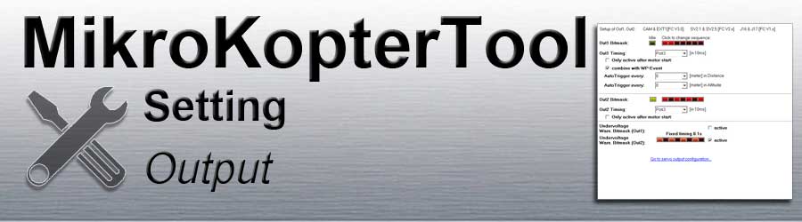
The following settings concern the switching outputs 1 + 2 of the FlightCtrl.
Out 1 => Switching outputs 1
Out 2 => Switching outputs 2
+5V (max 100mA) are permanently present at the switching output. GND is switched in each case.
If you want to switch consumers with a higher current consumption (e.g. LEDs),
an external circuit must be used for the supply (e.g. per ExtensionPCB).
If you want to trigger automatically via switching output 1 during a waypoint flight,
the WP automatic must be activated. Information about this can be found here: Link
Out 1
Switching output 1 (Out1) can be set here.
This output is usually used to trigger a photo camera.
Out1 Bitmask

The boxes at Out1 Bitmask can be activated / deactivated with the left mouse button.
Idle => Basic state of the switching output after switching on the copter
Box OFF = Switching output OFF
Box ON . = Switching output ON
Sequence => Switching sequence at the switching output
Box OFF = Switch off the switching output
Box ON . = Switch on the switching output
Out1 Timing
For Out1 Timing either a POTI or a fixed value (0-247) can be entered.
POTI
If a free channel is assigned to a button on the remote control, the associated POTI can be entered here.
If you press the button on the remote control, the switching output is switched ON / OFF.
The set sequence does not matter via the boxes! All red boxes can also be set on or off.
Example
Under Out1 Timing we have set a POTI
The red boxes were set this way: ON . OFF . ON . OFF . ON . OFF . ONOutput 1 is now switched using a button:
Button pressed (Channel fully switched) => As long as the button is pressed: Out1=ON
Button not in use (Channel out) => Out1=OFF
Fix value
A switching time (in 10ms per box) can be set with a fixed value (0-247).
Example 1
A 100 was entered as value under Out1 Timing (100x10ms = 1 Second)
The red boxes were set this way: ON . OFF . ON . OFF . ON . OFF . ONOutput 1 is now switched continuously:
1s ON . 1s OFF . 1s ON . 1s OFF . 1s ON . 1s OFF . 1s ON -> 1s ON . 1s OFF . 1s ON . 1s OFF . 1s ON . 1s OFF . 1s ON ... and so on
Example 2
AA 100 was entered as value under Out1 Timing (100x10ms = 1 Sekunde)
The red boxes were set this way: ON . ON . OFF . OFF . OFF . OFF . OFFOutput 1 is now switched continuously:
2s ON 2s ON . 5s OFF 5s OFF 5s OFF 5s OFF 5s OFF -> . 2s ON 2s ON . 5s OFF 5s OFF 5s OFF 5s OFF 5s OFF ... and so on
Only active after motor start

If a check is made under Only active after motor start, output 1 is only activated after the motors have started .
The output is deactivated again after the motors have been switched off.
combine with WP-Event
If a check is made under combine with WP-Event, output 1 is linked to the waypoint flight. A specialty applies here:
Out1 Timing -> POTI
If you set under Out1 Timing a POTI, you can switch with e.g. a 3way-button on your transmitter the function:
switch off => no function ("Waypoint Automatic" OFF) (during a waypoint flight the output 1 will not trigger a connected camera)
switch center => "Waypoint Automatic" ON (during a waypoint flight the output 1 will trigger the camera - depending on the settings in your waypoint flight)
switch ON => manual triggering
Out1 Timing -> value (0-247)
- A numerical input switches the switching output permanently
0 => no function ("Waypoint Automatic" OFF) (during a waypoint flight the output 1 will not trigger a connected camera)
127 => "Waypoint Automatic" ON (during a waypoint flight the output 1 will trigger the camera - depending on the settings in your waypoint flight)
INFO
If a POTI has been entered and a push button has been inserted on the remote control, the WP automatic can also be used.
Information about the setting can be found here: WaypointAutomatic- A numerical input switches the switching output permanently
AutoTrigger every

With this setting, the switching output can be triggered automatically
every X-meter permanently during the flight.
Auto Trigger every ...X... [meter] in Distance
Every "X" meter (in distance) the output Out1
will be trigger automaticallyAuto Trigger every ...X... [meter] in Altitude
Every "X" meter (Altitude) the output Out1
will be trigger automatically


Info
With automatic triggering every "X" meter, a fixed value of 10ms is used for triggering per box in the sequence. The sequence of the bit mask is completely processed once per triggering.Example: 1 trigger every "X" Meter
The red boxes were set this way: ON . OFF . OFF . OFF . OFF . OFF . OFFOutput 1 is now switched every "X" meter:
10ms ON . 60ms OFF 60ms OFF 60ms OFF 60ms OFF 60ms OFF
If the trigger is too fast for the camera used, it can also be enlarged:
Example: 1 trigger (longer)
The red boxes were set this way: ON . ON . OFF . OFF . OFF . OFF . OFFOutput 1 is now switched every "X" meter:
20ms ON 20ms ON . 50ms OFF 50ms OFF 50ms OFF 50ms OFF
Example: 2 trigger every "X" Meter
The red boxes were set this way: ON . OFF . ON . OFF . OFF . OFF . OFFOutput 1 is now switched every "X" meter:
10ms ON . 10ms OFF . 10ms ON . 40ms OFF 40ms OFF 40ms OFF
Out 2
Switching output 2 (Out2) can be set here.
This output is usually used to trigger/switch e.g. LEDs.
Out2 Bitmask
The boxes at Out2 Bitmask can be activated / deactivated with the left mouse button.
Idle => Basic state of the switching output after switching on the copter
Box OFF = Switching output OFF
Box ON . = Switching output ON
Sequence => Switching sequence at the switching output
Box OFF = Switch off the switching output
Box ON . = Switch on the switching output
Out2 Timing
For Out2 Timing either a POTI or a fixed value (0-247) can be entered.
POTI
If a free channel is assigned to a button on the remote control, the associated POTI can be entered here.
If you press the button on the remote control, the switching output is switched ON / OFF.
The set sequence does not matter via the boxes! All red boxes can also be set on or off.
Example
Under Out2 Timing we have set a POTI
The red boxes were set this way: ON . OFF . ON . OFF . ON . OFF . ONOutput 2 is now switched using a button:
Button pressed (Channel fully switched) => As long as the button is pressed: Out1=ON
Button not in use (Channel out) => Out1=OFF
Fix value
A switching time (in 10ms per box) can be set with a fixed value (0-247).
Example 1
A 100 was entered as value under Out2 Timing (100x10ms = 1 Second)
The red boxes were set this way: ON . OFF . ON . OFF . ON . OFF . ONOutput 1 is now switched continuously:
1s ON . 1s OFF . 1s ON . 1s OFF . 1s ON . 1s OFF . 1s ON -> 1s ON . 1s OFF . 1s ON . 1s OFF . 1s ON . 1s OFF . 1s ON ... and so on
Example 2
AA 100 was entered as value under Out2 Timing (100x10ms = 1 Sekunde)
The red boxes were set this way: ON . ON . OFF . OFF . OFF . OFF . OFFOutput 1 is now switched continuously:
2s ON 2s ON . 5s OFF 5s OFF 5s OFF 5s OFF 5s OFF -> . 2s ON 2s ON . 5s OFF 5s OFF 5s OFF 5s OFF 5s OFF ... and so on
Only active after motor start
If a check is made under Only active after motor start, output 2 is only activated after the motors have started .
The output is deactivated again after the motors have been switched off.
Undervoltage

In the settings under Misc we have the undervoltage warning.
If the undervoltage warning is active, the here "active" set output is automatically activated and a fast flashing pattern then takes place via this output.
INFO
Only the output with connected leds should be "active".
If you activate here also the switching output where a camera is connected, the camera will trigger in this interval during an undervoltage warning")