
Inhaltsverzeichnis
Info / Download
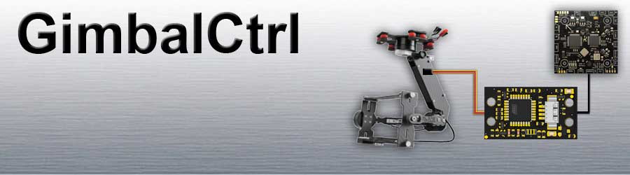
The GimbalCtrl can be used to control a brushless gimbal with AlexMos control.
The following functions are possible:
Control "Nick" (Pitch) BrushlessGimbal
Control "Roll" BrushlessGimbal
Control "Gier" BrushlessGimbal
- Trigger a photo camera (via an optional Shuttercable)
- Switch external consumers (e.g. LED via ExtensionPCB)
Starting scripts in the AlexMos control
- Precise pitch angle setting when flying waypoints
- Record the pitch and roll angles of the camera holder in a LOG file in the copter
Shoplink: GimbalCtrl
INFO
In order for the function of the GimbalCtrl to work, the software versions must match!
Otherwise there may be an error message or no function of the GimbalCtrl.
GimbalCtrl V1.02 |
|

GimbalCtrl V1.04 |
|
(Please use the MKUSB V3 for an update !!!)
Technical specifications

- Power +5V (über I2C)
- Dimensions 17,5 x 30mm
- Weight ~13g
- Cable length ~18cm
- Serial output gimbal control 8n1 / 9600 Baud
- "Trigger" output
- Switching output Out1 (GND or 3,3V)
- Switching output Out2 (GND or 3,3V)
GimbalCtrl - LED
The GimbalCtrl has a green and red LED. These indicate the following:
Green LED => permanently on + Red LED => flashes quickly
- Brushless gimbal not connected/not supplied with voltage
- Brushless gimbal was not recognized (Connection of gimbal or/and settings incorrect)
Green LED => blink slowly + Red LED => off
- Brushless gimbal was recognized correctly
If still no function
Software of the GimbalCtrl does not match the software version of the FlightCtrl (See info box above)
- The channels in the copter are incorrect
Connection
FlightCtrl

The GimbalCtrl is connected to the I2C bus of the FlightCtrl V3
using the 4-pin Molex cable.
Connection AlexMos

The second serial port "RC_SERIAL port" is used on the AlexMos board.
This has the advantage that the USB connection or an optional Bluetooth connection connected to the first serial input can be used independently of the GimbalCtrl.
The connection:
GimbalCtrl "GND" -> AlexMos "GND"
GimbalCtrl "Rx" -> AlexMos "RC_ROLL"
GimbalCtrl "Tx" -> AlexMos "RC_YAW"
Setting AlexMos

The setting of the second serial port "RC_SERIAL port" is done with a few settings.
INFO: Only from AlexMos Beta Version V2.66 can the baud rate for the first serial ports 1 and 2 be set separately !!
The serial RC input is activated under RC Settings
RC_ROLL pin mode => SBGC Serial API

The serial transmission speed for the GimbalCtrl must be set to 9600 baud.
You can change this under Hardware -> "RC_SERIAL port".
RC_SERIAL_port speed => 9600
The speed for Main serial port speed and UART2 port speed can remain set to 115200 baud.
So you have the full transmission speed with e.g. a Bluetooth connection to the gimbal.

If you use a 3-axis gimbal, the field at FollowYAW must also be activated under Follow mode.
Setting KopterTool
Nick-Roll-Gier
A total of 3 free channels are required to control functions Nick, Roll und Gier via the GimbalCtrl.
In this example, channels 8, 9 and 14 were each assigned to a potentiometer on the remote control.

The corresponding channels for Servo control - Nick and Servo control - Roll are now entered in the MikroKopter-Tool under Camera for the control of pitch and roll .
In addition, the entry Servo relativ is activated. This controls the pitch adjustment of the rocker on the gimbal.
If the potentiometer on the remote control is in the middle position, the rocker stops in the current position.
If the potentiometer is adjusted from the middle position, the rocker moves in the corresponding direction until the potentiometer is in the middle position again.
If this entry is activated, the gimbal rocker can also be tilted automatically to the exact degree during a waypoint flight.

The channel for yawing the camera bracket is set under CamCtrl at YAW Channel.
Functional test

After the brushless gimbal has been set and connected to the GimbalCtrl, it can be connected to the I2C bus of the FlightCtrl V3. The function can then be checked using the MikroKopter tool.
After the MikroKopter has been connected to the computer and supplied with power, the NaviCtrl button can be pressed in the main window of the MikroKopter tool.
In the central virtual display, the "GimbalCtrl" window is selected using the red arrows (left / right).
Display:
A - If the gimbal is set correctly, connect in the right way with the gimbal and also connected with the FlightCtrl, you can see the version number of your GimbalCtrl. The status (Stat
") is on "OK" and the angle of the gimbal (nick, roll, yaw) is displayed.
is on "OK" and the angle of the gimbal (nick, roll, yaw) is displayed.
(see picture "A")B - If the gimbal is set wrong, not or not right connected with the GimbalCtrl you can see the version number of your GimbalCtrl. But as the status shows "No Gimbal" and a fix Angle of -1°
(see picture "B")C - If there is no connection to the GimbalCtrl you see "Not connected".
(see picture "C")
Switching outputs
Optionally, up to 3 switching outputs (Out1, Out2, Trigger) can be used on the GimbalCtrl. This can trigger e.g. a photo camera or trigger a script in the AlexMos gimbal.
INFO: The switching outputs can be loaded with a maximum of 100 mA !!!
If you want to switch more loads (e.g. LED strips), the ExtensionPCB should be used. The switching outputs also work without a connected gimbal.

In this example, channels 15 and 16 were each assigned to a switch on the remote control.
These channels can then be assigned to the switching outputs OUT1 und OUT2 under CamCtrl.

The switching output "Trigger" on the "GimbalCtrl" is connected in parallel with the "switching output 1" of the FlightCtrl.
In this example, channel 10 was placed on a button and entered under Out1 Timing under "Outputs".
See also connection example Trigger
Switching examples

Example Out1 / Out2 => GND
If you want to switch LEDs or something else on/off, the switching outputs Out1 (Pad1) and Out2 (Pad8) can be used for this.
An LED can be connected directly, or you can use an ExtensionPCB and switch entire LED strips with more power.
INFO: Both switching outputs switch to ground (GND) and can be loaded with not more then 100mA.

Example Out1 / Out2 => 3.3V
If you want to start one or more scripts on the AlexMos gimbal, the switching outputs Out1 (Pad3) and Out2 (Pad4) can be used.
These outputs switch a voltage of 3.3V and can be connected to the inputs ADC1-3 of the AlexMos electronics.
An explanation of how to enter a script in the AlexMos control can be found on the manufacturer's website at:

Example Trigger
A camera can also be triggered via the GimbalCtrl using a Shuttercable.
For this, the shutter cable can be connected to pad "9" (trigger - is switched to ground) and pad "RT" (+ 5V).

Example Script + Trigger
If you want to trigger a camera via shuttercable from MikroKopter AND also via the AlexMos control via script, the connection is as described in the previous examples. In addition, only one of the outputs AUX1-3 of the AlexMos controller must be connected to the shutter cable.
Angle

If a waypoint flight is planned using the MikroKopter tool, a camera inclination can be entered for each waypoint.
With GimbalCtrl the entered value for the camera tilt is transferred as a direct angle value to the brushless gimbal.
The entry 90 ° is a direct look straight down and an entry of -90 ° is a straight look up.
INFO: In order for this function to be used, the Servo relative function must be activated in the MikroKopter settings.
See also Nick-Roll-Gier
LOG-File - TXT-File
The current inclination of the gimbal (for nick and roll) is continuously saved on the microSD card in the MikroKopter.

Two LOG files are available for evaluation:
GPX LOG file => "date".GPX
In this LOG file you can find all the telemetry data of the MikroKopter.
Under the "Gimbal" column are the values for the nick inclination and the roll inclination.
TXT Log file => "date".TXT
This LOG file essentially contains the position and angle data when taking a photo.
If e.g. 20 photos were taken during the flight, this LOG file contains 20 entries for the respective photo.
Separate supply for Copter / Gimbal
The GimbalCtrl has a high-impedance protective resistor on the GND connection.
If the supply voltage for the brushless gimbal is tapped by the MikroKopter, you do not have to do anything else.
If the connected brushless gimbal is supplied with its own battery, the GimbalCtrl may not have any function.
To ensure the function, the minus connection of the gimbal lipo and the ground connection (GND) of the copter must be connected.
INFO: Since there are different lipos and connections, we do not provide a ready-made solution for this connection!
Attention: Make sure that the polarity is correct when connecting.
Software Update


INFO: The GimbalCtrl already has the current software upon delivery !
For a software update, the GimbalCtrl will be connected directly to the MKUSB V3 via the Molex cable.
The GimbalCtrl is then supplied with power via the MKUSB as soon as the jumper is closed.
The current software can be found under Info / Download.
The new software can then be imported using the MikroKopter tool.
(see picture)